How to Use the Modbus TCP Interface
This article is for the ALTA Ethernet Gateway 4. There are slight differences in the Modbus TCP Interface of the Ethernet Gateway 3.
The Monnit ALTA Ethernet Gateway 4 offers a Modbus Transmission Control Protocol (TCP) Interface to access gateway and sensor information directly via Modbus TCP poll requests. Modbus TCP is the Modbus remote terminal unit (RTU) protocol with a TCP interface that operates over Ethernet. This interface can be used without the Default Server Interface (iMonnit Software) active or as a standalone interface. The Interface’s standalone configuration enables the gateway on a local private network without iMonnit by polling the gateway via Modbus TCP requests.
The Modbus TCP Interface is read-only. Therefore there is no way to send data or configure the gateway or sensors through the Modbus TCP Interface.
When operating an ALTA Ethernet Gateway on a private network without iMonnit, the gateway must be unlocked, and there are certain limitations in configuring sensors. Please review the article below for details on using the gateway on a private network with the Default Server Interface disabled. If you are using the Modbus TCP Interface in conjunction with iMonnit Software (such as iMonnit.com), there’s no need to unlock your gateway. Using the Ethernet Gateway 4 on a private MODBUS TCP or SNMP Network.
Menu - Skip To
- Activate the Modbus TCP Interface
- Add Sensors
- Modbus Registers
- Test the Modbus TCP Interface
- Update the Gateway Firmware
Activate the Modbus TCP Interface
The Modbus TCP Interface on an Ethernet Gateway is inactive by default. There are two ways to activate the interface. You can activate it through iMonnit or locally using the HTTP Interface (local configuration page).
To effectively use your gateway with the Modbus TCP Interface, you’ll need to poll your gateway at the same IP address. Therefore you’ll need to configure your gateway to operate with a static IP address.
Activate the Modbus TCP Interface Using iMonnit
These steps assume that your gateway is in your iMonnit account.
- Log into iMonnit.
- Select Gateways from the primary left-hand menu.
- Select the gateway to activate the Modbus TCP Interface.
- Select the Settings tab (gear icon) in the top navigation bar.
- Select the Interface sub-tab (in the gray area toward the center of the screen).
- Toggle the switch for “Activate MODBUS Interface” to On.
- Click the Save button.
Click the Continue button.
The Interface will be enabled on the next gateway check-in and can be polled to retrieve Modbus data.
With the default configuration, the TCP Timeout Minutes is 5 minutes, and the Port number is 502. If you need to modify these configurations, you can do it under the Modbus sub-tab that now appears in the gateway settings.
Activate the Modbus TCP Interface Using the HTTP Interface (local configuration page)
Another way of adjusting your Modbus TCP settings is through the gateway’s HTTP Interface (local configuration page) through a browser. The local interface is accessible from a web browser on the same local network. This interface can be enabled from iMonnit, or locally. For information on accessing the HTTP Interface through a browser, whether your gateway is communicating with iMonnit or not, see the following articles:
Local Configuration Page (HTTP Interface) of the Ethernet Gateway 4 through iMonnit Online
Ethernet Gateway 4 - Accessing local configuration page (HTTP Interface) Locally
- Launch a web browser, and navigate to the IP address of your gateway.
- Select the Data Interfaces tab.
- Select the MODBUS TCP Interface tab.
- Select the Active option.
Enter your desired configurations.
Data Expiration – This is the number of minutes that data can be received from a register on the Modbus TCP Interface. Once the age of the data held in the register has reached this threshold, it is cleared.
Socket Timeout – The amount of time in seconds the gateway waits for communication from the server before the connection is refused.
Listening Port - This is the number for where the server data from the gateway is received.
Click the Save Changes button.
The gateway will reinitialize, and when it is up and running, the Modbus TCP Interface will be active.
Add Sensors
There are two ways to add sensors to the gateway’s wireless sensor network.
- Use iMonnit to add the gateway and sensors to a network.
- If your gateway doesn’t use iMonnit (Default Server Interface disabled), you can add sensors using the HTTP Interface (local configuration page).
We recommend that if you’re using iMonnit, you add devices through the software and not use the local interface.
The Sensor List (Wireless Device Network) of a gateway has some important behaviors. You can find detailed information on the Sensor List in the following article: Understanding Gateway Sensor Lists.
Understanding the Reform command and how it affects the gateway’s Sensor List is also important. Information on the Reform command can be found in this article:Reform Gateway Network.
Add Sensors Using iMonnit
If you haven’t done so, you can build your wireless network in iMonnit. This is done simply by adding your gateway and sensors to the same network. For step-by-step instructions on setting up your sensors and gateways, please visit this article: Getting Started Registering Devices.
Add Sensors Using the HTTP Interface (local configuration page)
Alternatively, you can add sensors using the gateway’s HTTP Interface (local configuration page). For information on accessing the gateway’s local configuration page, see the following article: Ethernet Gateway 4 - Accessing local configuration page (HTTP Interface) Locally.
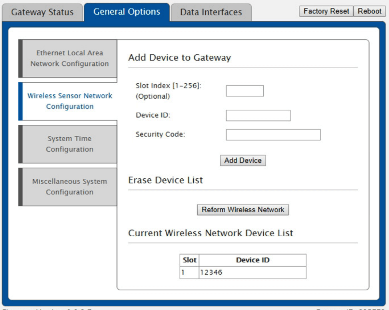
To add sensors using the HTTP Interface (local configuration page):
- Access the gateway’s HTTP Interface through a web browser.
- Click the General Options tab.
- Click the Wireless Sensor Network Configuration tab.
- Enter the Device ID in the Device ID field.
- Enter the Security Code in the Security Code field.
- If you manually configure the Slot, enter the value for the desired Slot Index (otherwise, leave this field blank).
Click the Add Device button.
After adding the device to the Wireless Sensor Network, your gateway will allow the device to join and report data in the corresponding registers for that slot.
Modbus Registers
Modbus registers are numerical identifiers referring to 16-bit data stores. The Modbus TCP Interface will store all data values in 16-bit registers. In some cases where a value is greater than 16 bits (such as the device ID, which is 32 bits), the value is spread across multiple registers and must be concatenated to interpret the data.
Five registers can be polled with the Ethernet Gateway 4 to provide gateway information (the Ethernet Gateway 3 has four to poll).
There are 16 registers for each sensor added to the gateway’s Sensor List (Eight of which are data registers where the sensor provides data from readings).
Monnit ALTA Gateways are Modbus servers. The gateway does not offer a configuration for a server ID.
Gateway Registers
These registers offer basic information on the gateway and it’s current configuration as displayed below:
Field: Gateway ID_High
Description: The first 16 bits of a 32-bit serial ID number.
Holding Register: 40001
Data Address: 0
Field: Gateway ID_Low
Description: The last 16 bits of a 32-bit serial ID number.
Holding Register: 40002
Data Address: 1
Field: Gateway Version - Revision + Major
Description: The gateway firmware Revision and Major version numbers (1 byte each)
Holding Register: 40003
Data Address: 2
Field: Gateway Version - Minor + Release
Description: The gateway firmware Minor and Release version numbers (1 byte each)
Holding Register: 40004
Data Address: 3
Field: Gateway Device Count
Description: The number of devices in its wireless network
Holding Register: 40005
Data Address: 4
Sensor Registers
SeeEthernet Gateway 4 - MODBUS TCP Sensor Register Definitionsfor details on interpreting sensor data in the Ethernet Gateway 4 MODBUS TCP Interface.
The gateway stores sensor data in consecutive banks of 16 registers for each sensor corresponding to the slot to which the sensor is assigned. Eight registers provide sensor information, and eight are reserved for data from sensor readings. Depending on the sensor type, not all of the eight registers will be utilized (some sensors, such as ALTA Temperature Sensors, may only use the first data register while the remaining registers are unused). Any data field not utilized will hold a 0 value.
The registers and their data fields are outlined below:
Field: Sensor ID_High
Description: The first 16 bits of a 32-bit serial number
Holding Register: 40101
Data Address: 100
Field: Sensor ID_Low
Description: The last 16 bits of a 32 bits serial ID number
Holding Register: 40102
Data Address: 101
Field: Device Type
Description: The unique type identifier for the sensor profile
Holding Register: 40103
Data Address: 102
Field: Data Age
Description: The number of seconds that have elapsed since the last data was retrieved
Holding Register: 40104
Data Address: 103
Field: Device Active
Description: 0 indicates no data for this slot, 1 indicates there is data for this slot
Holding Register: 40105
Data Address: 104
Field: Is Aware
Description: Becomes aware when a sensor threshold has been breached
Holding Register: 40106
Data Address: 105
Field: Voltage
Description: Battery voltage in centivolts
Holding Register: 40107
Data Address: 106
Field: RSSI
Description: Signal Strength Indicator, RSSI value as percentage signal strength
Note: Firmware version 1.0.6.5 and earlier report the percentage as the inverse percentage. A 75% signal reports a 25 value, 66% reports 34, 55 reports 45, etc.
Holding Register: 40108
Data Address: 107
Interpretation:
- -115 and lower = 0%
- -111 = 10%
- -107 = 20%
- -103 = 30%
- -99 = 40%
- -94 = 50%
- -90 = 60%
- -80 = 70%
- -70 = 80%
- -60 = 90%
- -50 and above = 100%
Field: Data 1
Description: Sensor Data Field 1
Holding Register: 40109
Data Address: 108
Field: Data 2
Description: Sensor Data Field 2
Holding Register: 40110
Data Address: 109
Field: Data 3
Description: Sensor Data Field 3
Holding Register: 40111
Data Address: 110
Field: Data 4
Description: Sensor Data Field 4
Holding Register: 40112
Data Address: 111
Field: Data 5
Description: Sensor Data Field 5
Holding Register: 40113
Data Address: 112
Field: Data 6
Description: Sensor Data Field 6
Holding Register: 40114
Data Address: 113
Field: Data 7
Description: Sensor Data Field 7
Holding Register: 40115
Data Address: 114
Field: Data 8
Description: Sensor Data Field 8
Holding Register: 40116
Data Address: 115
The sensor in the next slot will use the following bank of 16 registers. Registers 40117–40132 are the next bank of 16 registers for the sensor in slot 2, the sensor in slot 3 will use registers 40133–40148, and so on for the number of sensors registered in the gateway.
Concatenate Split Registers
For data values that occupy more than a single register (such as the device ID, which is 32 bits), the value must be concatenated (linked together) to interpret the full value. See the example below:
In this example, we will look at a sensor with the ID 315234 registered to slot 2.
To get the ID High and ID Low, you would poll registers 40117 and 40118 (the first two registers in the bank of 16 for the sensor in slot 2). Polling these registers would give the following values if polled as decimal integers:
Register 40117: 3
Register 40118: 53090
You would then convert the values to hexadecimal. Doing so gives you the following values:
Register 40117: 3
Register 40118: CF62
You would then concatenate the two values to get 3CF62.
Converting the hexadecimal value of 3CF62 to decimal gives you 315234 the sensor ID in a decimal integer.
Humidity Sensor Example
We will use an ALTA Humidity Sensor to demonstrate what values you might expect to see and how to interpret these values. Consider a Humidity Sensor with ID 315234 registered to slot 2 with the following details:
Last checked in: 5 minutes ago
Aware: Not Aware
Signal: 60%
Battery Level: 90%
Signal Level: 80%
Reading: 72.5° F with 42.5% humidity
To see all 16 sensor registers, you would poll registers 40117–40132. Doing so would result in the following results when polled as decimal values:
40117: 3 (first part of the 32-bit sensor ID—3 in decimal = 3 in hexadecimal)
40118: 53090 (second part of the 32-bit sensor ID—53090 in decimal = CF62 in hexadecimal—concatenate ID high and low to get 3CF62 which equals the sensor ID 53090)
40119: 48 (device type = 48—according to the following call, type 48 is a Humidity Sensor: https://www.imonnit.com/xml/GetApplicationID)
40120: 300 (data age is 300 seconds—the sensor last communicated with the gateway 300 seconds ago)
40121: 1 (sensor is Active since the value is 1 and not 0)
40122: 0 (sensor is not in Aware State since the value is 0 and not 1)
40123: 316 (battery is full as the voltage is reported as 316 = 3.16 Volts)
40124: 60 (signal is 100 as RSSI is -60 RSSI)
40125: 4250 (humidity is reported as 425 = 42.5 percent
40126: 2250 (temperature is reported as 2250 22.5°C)
40127: 0 (this sensor type does not report data on data registers 3–8)
40128: 0 (this sensor type does not report data on data registers 3–8)
40129: 0 (this sensor type does not report data on data registers 3–8)
40130: 0 (this sensor type does not report data on data registers 3–8)
40131: 0 (this sensor type does not report data on data registers 3–8)
40132: 0 (this sensor type does not report data on data registers 3–8)
40132: 0 (this sensor type does not report data on data registers 3–8)
Test the Modbus TCP Interface
If you activate the Modbus TCP Interface on your gateway, you can test it with a lightweight tool developed by Schneider Electric. Download this tool at the following link: Schneider Electric Testing Tool.
Instructions for testing the Interface can be found below.
- Ping the gateway’s IP address from your PC to confirm you get a successful response.
- Disable any firewall or security software that might block requests on the used port (TCP port 502 by default).
- Download and launch the Tester.exe application.
- Confirm the Port is set to TCP/IP.
- Enter the gateway’s IP Address in the TCP/IP Address or URL field.
- Confirm Sample Mode is set to Manual.
- Leave Timeout in ms: set to 20000.
- Leave Sample Rate in ms: set to 1.
- Leave Data Type set to Holding Registers (R03/W16).
- Leave Server ID at the default setting.
- Enter 1 for the Starting Register.
- Enter 5 for the number of Registers.
- Click the Read button.
You should return values for registers 1–5. These registers correspond to the gateway information.
To poll data from the sensor in slot 1, you would change the Starting Register to 101 and the # of registers to 10 (note: this utility can only display a maximum of 10 registers at a time). If you receive a timeout or similar error, the utility did not successfully communicate with the gateway’s Modbus TCP Interface.
Update the Gateway Firmware
There are important updates for the Modbus TCP Interface for the Ethernet Gateway 4. Therefore it is essential to ensure your gateway is running current firmware before building your sensor network with your Ethernet Gateway’s Modbus TCP Interface.
Updating the gateway’s firmware may reset the gateway’s configurations to default settings. If your gateway is programmed with a static IP address, it may be cleared, and DHCP (re)enabled. You should be prepared to reconfigure the gateway on a network with DHCP enabled if you perform an update on a gateway with a static IP address. However, gateway firmware version 1.0.5.1 and later can restore configurations after being updated.
Keeping the gateway’s firmware updated is an important step to resolving some unexpected issues. To update the firmware, the gateway must be checking in with iMonnit. You can update your gateway’s firmware by following these steps:
- Log into the iMonnit Online portal with an Administrator login.
- Click the Gateways link in the left-hand sidebar.
- Click the Gateway you wish to update.
- Click the Settings tab (gear icon).
- Click the Commands sub-tab.
- If an update is available, you will see a blue button labeled Update, click it.
- The gateway’s firmware will update to the most recent version on its subsequent check in. Updates generally take less than 10 minutes, and the gateway will check in normally after the update is complete.
Conclusion
The Modbus TCP Interface offers versatility in integrating Monnit devices with your application. While there are many details and configurations to consider when implementing an Ethernet Gateway with the Modbus TCP Interface, this article should get you started with your integration. For related inquiries, feel free to contact Monnit Support.