Connecting the 0-20 mA Wireless Sensor to Your 4-20 mA Device
Monnit provides a number of mounting options for its sensor technology. Screws and double-sided tape are included in each deployment kit, which should allow you to mount Monnit’s hardware to most materials.
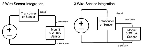
When hooking the 0-20 mA wireless sensor to your device please follow these instructions. For 2 wire sensor integration, connect the red wire from the Monnit sensor to the signal wire of your device, then connect the black wire to the ground. For 3 wire sensor integration, connect the red wire from the Monnit sensor to the signal wire of your device, then connect the black wire to the common ground.
The Monnit 0-20 mA Sensor cannot survive more than 4VDC directly across the sensor. If the Monnit Sensor is connected directly to 24VDC, it will burn out and cause irreparable damage. The way the mA sensors work is they only produce enough voltage to get the current they need. At a full load of 25mA, our unit will only experience 1.5V of the full load. The leads of the 0-20 mA sensor have 51 Ohms of resistance.
Edit Measurement Settings
After the sensor has been added to your account, you can apply a custom Scale as to translate the mA readings to your appropriate two point Scale. This can be done with the following steps.
• Under the “Scale” section, you can customize the format for your application.
• Enter the appropriate 4 mA (low reading value) and 20 mA (high reading value).
• Enter your custom application’s measurable unit type in the “Label” field.
• Select Save.
After applying a Scale, the “Readings” tab, you should display see the data in your custom format once your sensor starts reporting mA readings on its Heartbeats.