How to Install the Soil Moisture Sensor
The ALTA Soil Moisture Sensor is easy to install when you know its external features and the supplies and tools you need to complete the installation process.
Sensor Overview and Installation
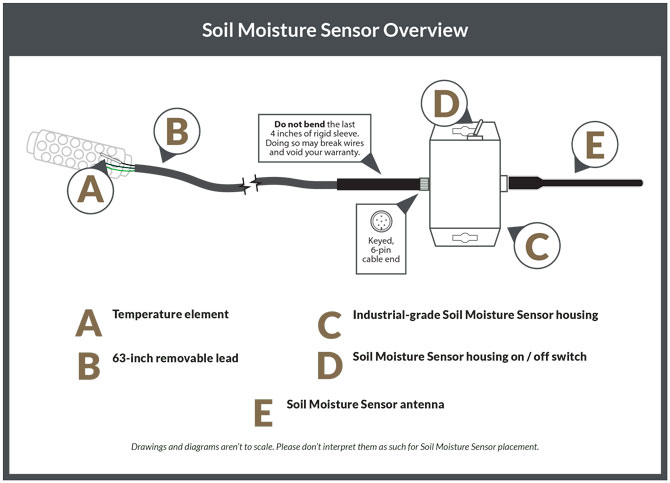
The following diagram explains the five main components that make up the Soil Moisture Sensor. Please review the diagram to understand the sensor’s external components, including:
- A - The resistive granular matrix and temperature element
- B - 63-inch removable lead
- C - Industrial-grade (IP65 Nema Rated) sensor housing
- D - On/off switch
- E - Radio antenna
Preparing the Soil Moisture Sensor for Installation
To install the Soil Moisture Sensor, we recommend using the following supplies and tools (not sold with the sensor).
Supplies:
- PVC pipe to insert the Soil Moisture Sensor’s soil probe in the ground and on
- which to mount the Soil Moisture Sensor’s housing.
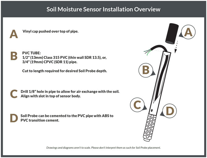
- 1/2" (13mm) Class 315 PVC (thin wall SDR 13.5), or
- 3/4" (19mm) CPVC (SDR 11) pipe
- ABS to PVC transition cement
- A vinyl cap for the PVC pipe
- Three zip ties
Tools:
- Drill with 1/8" bit
- Hacksaw
- 7/8" rod or auger, 1" rod or auger for abrasive soils.
Soil Moisture Lead Preparation and Installation
The soil moisture lead is designed to be buried directly in the soil but we recommend using a PVC pipe and vinyl sealing cap as indicated in the following installation diagrams. If burying directly in the soil ensure the soil moisture element is buried completely and water cannot easily flow down from the top of the PVC pipe to the element’s lead. If the sensor is not buried well and water can flow down the lead, the sensor may become inadvertently saturated and provide high moisture or shorted readings. Before burying the lead always perform wetting process first.
Wetting Process: Soak the sensors overnight in irrigation water. Always install a wet sensor. If time permits, slowly wet the sensor by partially submerging (no more than halfway, 1 to 2") for 30 minutes in the morning and let dry until evening, wet for 30 minutes, let it dry overnight, wet again for 30 minutes the next morning, and let it dry until the evening. Soak it over the next night and install WET. This will improve the sensor’s response in the first few irrigations
Physical Installation: Make a sensor access hole to the desired depth with a 7/8’’ (22mm)O.D. rod/auger. Fill the bottom of the hole with a thick slurry made of soil removed from thehole and water, then firmly push the sensor down into the mud in the bottom of the hole. This will “grout in” the sensor to ensure maximum surface contact between the sensor surface and the surrounding soil. Alternatively, the sensor can be firmly pushed to the bottom of the access hole as long as it is a tight enough fit to ensure adequate contact; a snug fit in the soil is absolutely necessary.
A length of 1/2’’ Class 315 PVC (thin wall SDR 13.5) or 3/4’’ CPVC (SDR 11) pipe will fit snugly over the sensor’s collar and can be used to push in the sensor. This PVC can be solvent welded to the sensor collar with a transition solvent PVC to ABS cement. If the PVC pipe is not left on the sensor (not-recommended), then backfill the hole so the sensor is buried.
It is important that water doesn’t run down the sensor lead and reach the sensing element directly so it is recommended to bury a small horizontal section of the lead (6 to 12" of lead under 3 to 6" of packed soil). If PVC is left on, then compact soil around the surface to seal off the hole. The PVC acts as a conduit for the sensor wires. Be sure to cap off or tape the top of the pipe, so surface water will not infiltrate to the sensor and give a false reading. Drill a small hole at the bottom of the pipe to allow any trapped water to drain away. Label each sensor lead to indicate sensor depth.
It is important that the sensor is located in the active root system of the crop.
Marking the installation with a “flag” will facilitate finding them later.
Installing in Coarse or Gravelly Soils: For very coarse or gravelly soils, an oversized hole (1" - 1.25" [25 mm - 32 mm]) may be needed to prevent abrasion damage to the sensor membrane. In this case, auger a hole to the desired depth and make a thick slurry with the soil and some water, as described above. Fill the hole with this slurry and then install the sensor.
Another method of installing sensors in difficult gravelly soils, or at deeper settings is to use a “stepped” installing tool (see Fig. 3). This makes an oversized hole in the upper portion and an exact size hole (sensor is 7/8" [22 mm] O.D.) for the lower portion where the sensor is located. The hole must be carefully backfilled and tamped down to prevent air pockets, which could allow water to channel down to the sensor.
Mounting the Sensor Housing
We recommend installing the prepared soil probe with a PVC pipe into the ground and thenattaching the sensor’s housing to the PVC pipe. You have the following two options to mount the sensor’s housing to the PVC pipe:
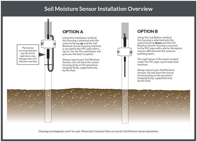
We highly recommend option A. Although not recommended, at your discretion, you may choose to mount the sensor’s housing to a nearby post if the length of the lead allows.
Sensor Removal and Storage: If sensors are removed, clean and dry them. They can bestored indefinitely in a clean, dry location. Switch them off to save battery power. Alwaysrewet by following the process outlined above before re-installation.
Further Reading
How the Soil Moisture Sensor Works
Soil Moisture Sensor Installation by Crop Type
Interpreting Soil Moisture Sensor Data