How to Configure and Install an ALTA Current Meter
Sensor Overview
Monnit ALTA Wireless AC and Three-Phase Current Meters measure the root mean square (RMS) current of an alternating current (AC) system using a current transducer (CT). To monitor, the CT wraps around the “hot” wire of a single (AC) or three-wire (hot, common, ground (optional)) power system.
The settings configuration and installation is nearly the same whether it’s an AC or Three-Phase Current Meter.
Settings to Configure
- Minimum Threshold—Assessments below this value will cause the meter to enter the Aware State and report data if not already in the Aware State.
- Maximum Threshold—Assessments above this value will cause the meter to enter the Aware State and report data if not already in the Aware State.
- Averaging Interval—Time, in seconds, for how often the meter will assess within its Heartbeat. The measurements taken will be averaged together to calculate the Average Current reading the meter produces.
- Accumulate—If Off, only the Accumulated Current or Power consumed during a single Heartbeat will be reported. If On, the energy consumed during the current Heartbeat will be continually added to the previously reported measurements.
- Show Full Data—Only the Accumulated Current or Power is displayed if Off. If On, Average, Maximum, and Minimum Current measurements are also displayed.
Additional Features and Options
- Scale—Changes the measured value from Accumulated Current (Amp-hours) to Power (Watt-hours or Kilowatt-hours) and permits the setting of a system voltage (120 VAC for US, 240 VAC for EU, etc.).
- Calibration—Enables the calibration of the current for more precise in-application measurements.
Installation Steps
Note: If this is your first time setting up your Monnit system, you must first set up your iMonnit account and connect your ALTA Gateway to iMonnit before registering your sensor. See this article for steps outlining how to get started: Creating an iMonnit account.
Step 1.
Remove the Current Meter from the package. If installing an industrial meter, attach the antenna.
Step 2.
Register the meter in iMonnit. Do not install the batteries until iMonnit tells you.
Step 3.
Determine the meter’s installation location. We recommend placing the meter in the location and making sure it reports to the gateway before final installation. See this article if you’re using an ALTA Site Survey Tool to perform a site survey to determine sensor installation location.
Step 4.
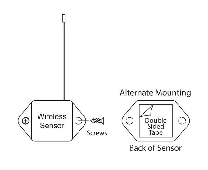
After ensuring that the meter is communicating with the gateway, mount the meter in a location that will leave enough room for the CT(s) to clip on the power wire(s). Mount the meter with the provided screws or double-sided tape.
Step 5.
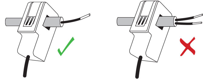
Attach the CT(s) to the power wire(s) you wish to monitor.
The CTs are designed to clip around a single current-carrying wire. Ensure that the CT is NOT wrapped around a cable with a common and live wire; otherwise, the sensor will read approximately 0.00 amps. See the diagram below for appropriate CT installation.
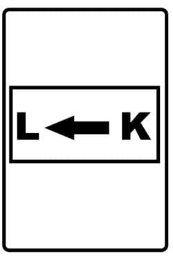
Some CTs come with a direction arrow, it does not matter which direction the current is flowing when you attach the CT