Sensor State vs. STS
Summary
This document was created to illustrate how to explain the difference between STS and State in the exported data of a sensor. It can also help determine the reason for specific error codes used and the different states a sensor can be in.
State or Status Byte (The word State is used throughout for consistency.)
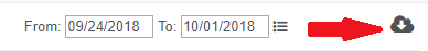
The State byte is sent as a part of every single sensor data message (SDM), and the Self-Test Status (STS) nibble makes up half of that byte. You can check the State byte in iMonnit by going into the History tab for the sensor and clicking the Export icon, which you will find to the right of the date picker. The data will be in the column titled "Sensor State."
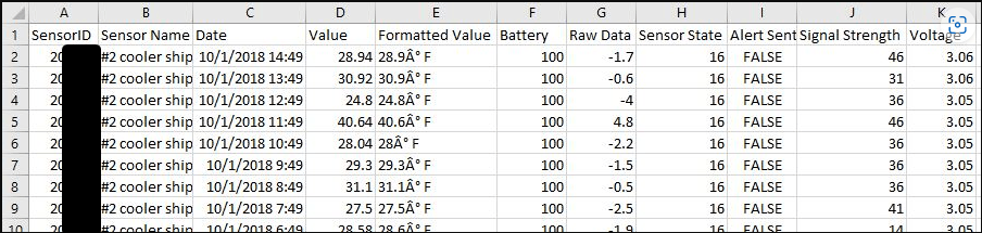
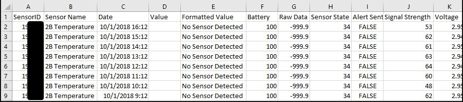
The resulting .csv file will look something like this:
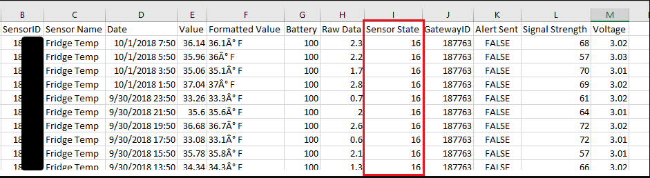
Binary Sensor data is stored in multiple data registers in the database, and the State data is stored in one register. The decimal value of the Sensor State is what you will see after the data is formatted for the customer to view and then exported.
The binary representation of one register = AAAA bcde (0001 0110, etc.); in this instance, the State Byte
The first four bits, AAAA = the STS bits/nibble or the Self-Test Status. This value is specific to the sensor profile and is often used to indicate the sensor's error states and other conditions. If the sensor is working correctly, the value will usually be 0.
The last four bits break down as follows:
b = Reserved – This bit is currently undefined across all sensors.
c = Disabled – If this bit is 1, the sensing functionality is disabled, but the radio continues to work.
d = AwareActive – Aware State is Active if this bit is 1, and it is unaware that it is 0.
e = TestActive – The test state is active. Reading sensors will send this test message ten times on power up with an interval of 30 seconds between messages (With some Generation 1 sensors and ALTA sensors with older firmware, the test message is sent four times on power up with an interval of 30 seconds between messages). Trigger sensors will send the TestActive only once when power is first applied.
Basic Binary Information:
1 Byte = 8 Bits
4 Bits = 1 Nibble
1 = On, True, Yes, etc.
0 = Off, False, No, etc.
Examples of how this information can be used:
Temperature Sensor, functioning normally, not in an aware state:
State Byte = 16
Convert to Hex = 10
Convert to binary = 0001 0000
The first four bits = 0001: the STS bits/Nibble (Indicates temp sensor has not been calibrated)
The last four bits = 0000: 0 (reserved), 0 (Not disabled), 0 (Not aware), 0 (Test not active)
Open/Closed Sensor, opening and closing, in and out of the aware state
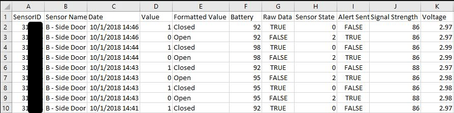
Not Aware on Open
State Byte = 0
Convert to Hex = 0
Convert to binary = 0000 0000
STS bits/Nibble = 0000:
The last four bits = 0000: 0 (reserved), 0 (Not disabled), 0 (Not aware), 0 (Test not active)
Aware on Closed
State Byte = 2
Convert to Hex = 2
Convert to binary = 0000 0010
STS bits/Nibble = 0000
The last four bits = 0010: 0 (reserved), 0 (Not disabled), 1 (Aware), 0 (Test not active)
Temperature Sensor, in an error state, No Sensor Detected
State Byte = 34
Convert to Hex = 22
Convert to binary = 0010 0010
STS bits/Nibble = 0010 (See chart below): Error Reading of No Sensor Detected
The last four bits = 0010: 0 (reserved), 0 (Not disabled), 1 (Aware), 0 (Test not active)
In this case, the sensor is in an error state, which introduces the addition of other values that need to define the error further. In the case above, the other value is -999.9, indicating the error "No Sensor Detected."
The following table outlines profile-specific STS values and what they mean:

Last updated on 10/25/2023