Principles of operation
The Monnit Current Meters are designed to provide current readings as they relate to time. The main value a Monnit Current Meter reports is Ah (Amp-hours). This represents amps expended per hour. Loosely speaking, it allows you to keep track of the amount of power that is being used over time.
In addition to measuring Ah, the sensor also reports the maximum, minimum, and average amps detected during the Heartbeat period, and the Duty Cycle (percentage of time during the last Heartbeat, the amperage measured above the configured Duty Cycle threshold).
The most frequent Measurement Interval this sensor can accurately engage is 5 seconds. Therefore, the most frequent Heartbeat that should be configured for this sensor is 5 seconds in any configuration.
Note: The Monnit Current Meters do not report instantaneous current. The samples taken during each Measurement Interval are used to sample instantaneous current and also used to trigger the Aware State readings if the Measurement Interval detects a current outside of the threshold. But the readings reported by the sensor do not include the instantaneous current sampled at the time the Heartbeat is reported.
Example Applications
- Power Monitoring
- Amperage surge monitoring
- Machine Monitoring
- Three-Phase Motors
- Power Availability Monitoring
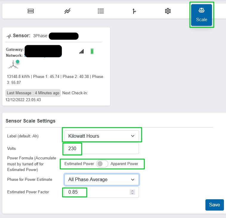
Scale
The Current Meter offers a Scale tab which will allow you to select the specific scale by which a user wishes to deliver the data in the iMonnit Online Portal. The available scales are:
- Amp Hours
- Watt Hours
- Kilowatt Hours
- Megajoule (Three Phase Current Meters)
To enable Watt Hours or Kilowatt Hours, the User will need to enter the Voltage in the “Volts” field after selecting the desired scale. The calculations are calculated using an implied static voltage. These scale will not yield accurate readings if the voltage present on the line is not consistent at the voltage entered in the portal.
Apparent vs. Estimated Power
The Scale of Three Phase Current Meters offers the option to select Apparent Power or Estimated Power to configure the Power Factor. A toggle switch allows you to select which option is desired. Apparent Power represents the Current in its hypothetical full power. Estimated Power represents the estimated power after heat dissipation and other factors that deplete the power of the current. After toggling to Estimated Power, a field will appear in which to enter the Estimated Power Factor. This is generally a decimal between 0.1 to .99. Common Power factors are 0.80, 0.85, 0.90, or 0.95. A drop-down menu will also appear that will prompt you to select which phase (all three by default) should be used for the power estimate.
Note: The Estimated Power is accurately delivered only if the Accumulate feature is set to off.
Configurations
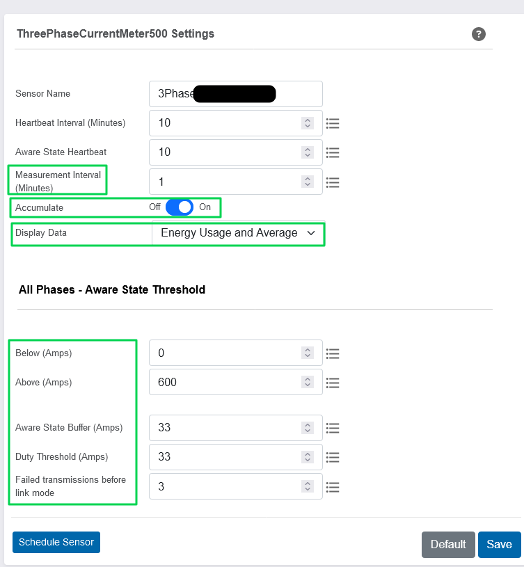
Measurement Interval/Averaging Interval - The Monnit Current Meter sensors operate by taking samples of the instantaneous current over a Heartbeat period, using those samples to calculate the current used over time (Ah reading), and reporting that value on its Heartbeat. The Measurement Interval is the frequency at which those samples occur. These calculations are used to arrive at the readings reported on the Heartbeat. The minimum suggested Measurement Interval is 5 seconds (0.083 minutes). Any Measurement Interval more frequent than this can result in incorrect calculations.
Default: 5 Seconds/0.083 minutes
Display Data/Show Full Data Value - In addition to using the samples taken on each Measurement Interval for the Ah calculation, these values are surveyed on the Heartbeat to provide a Minimum/Maximum/Average current value which is also reported on the Heartbeat. By default, these values are hidden; the Show Full Data Value toggle can enable these readings to be displayed on each Heartbeat (as well as the Duty Cycle).
Default: Hide/Off/Energy Usage
Heartbeat Interval - How often the sensor communicates with the gateway if no Aware activity is recorded.
Default: 120 minutes
Aware State Heartbeat - How often the sensor communicates with the gateway while in the Aware State.
Default: 120 minutes
Accumulate - Reports the aggregated Ah by adding the current Ah reading to previous Ah reading, with a rolling tally.
Default: Off
Below (Amps)/Above (Amps)/Threshold Min/Max - These values configure the Aware State Threshold. These thresholds are based on the instantaneous amp readings taken during the Measurement Intervals. Therefore, if the instantaneous current sampled during a Measurement Interval is outside of the configured threshold, it will trigger an Aware reading, and the sensor will report an Aware State Heartbeat to the gateway at that time.
Default: 0/Max
Note: The resolution for the Min/Max values is lower than the Avg calculation for Three Phase Current Meters. For 500 A, the resolution is 3 A; For 150 A, and 20 A versions, it is 1 A. Therefore, it is not uncommon to see the Min value reported to be greater than the Avg value because of this calculation difference.
Duty Threshold - Values above this threshold will contribute to the average current/power.
Ex: If the Duty Threshold configuration is set to 10 amps or Watts and the current is below 10 amps or watts for the entire Heartbeat, the Duty Cycle will be reported as 0%. If the Current detected during the Measurement Intervals is 10 amps or above for 50 % of the time during the previous Heartbeat period, the Duty Cycle will be reported as 50%.
Default: 0
Aware State Buffer - A buffer to prevent the sensor from bouncing between Standard Operation and Aware State when the assessments are very close to a threshold. For example, if a Maximum Threshold is set to 90° and a Hysteresis of 1°, then once the sensor takes an assessment of 90.0° and enters the Aware State, it will remain in the Aware State until the temperature readings drop to 89.0°. Similarly, at the Minimum Threshold, the temperature will have to rise a degree above the threshold to return to Standard Operation.
Default: 0
Failed transmissions before link mode - The number of transmissions the sensor sends without response from a gateway before it goes to battery saving link mode. (Zero will cause the sensor to never join another gateway, to find a new gateway, the battery will have to be cycled out of the sensor.)
Default: 3
Range and resolution
Reference: Current Meter Specifications Sheet
0-20 Amp CT Specifications
Absolute max CT current 50 Amps RMS (A rms)
Maximum accurate CT current 20 A rms
Frequency range 50 - 100 Hz
Accuracy +/- (2% +.07 A rms)**
Calibrated accuracy with appropriate offset +/- (1% + .035 A rms)**
Offset limits -1.27 to + 1.27 A rms (default set to +0.1 A rms) ***
Measurement resolution ~.01 A rms
Typical Deadband ~0.1 A rms
0-150 Amp CT Specifications
Absolute max CT current 200 Amps RMS (A rms)
Maximum accurate CT current 150 A rms
Frequency range 50 - 100 Hz
Accuracy +/- (2% + .4 A rms)**
Calibrated accuracy with appropriate offset +/- (1% + .2 A rms) **
Offset limits -1.27 to + 1.27 A rms (default set to + 0.3 A rms) ***
Measurement resolution ~0.1 A rms
Typical Deadband ~0.3 A rms***
0-500 Amp CT Specifications
Absolute max CT current 600 Amps RMS (A rms)
Maximum accurate CT current 500 A rms
Frequency range 50 - 100 Hz
Accuracy +/- (2% + 1.4 A rms) **
Calibrated accuracy with appropriate offset +/- (1% + .7 A rms) **
Offset Compensation Limits -327.68 to + 327.68 A rms (default set to + 1.45 A rms) ***
Measurement resolution ~0.3A rms
Typical Deadband ~1.45 A rms ***
*Circuits cannot withstand negative voltage. Please take care when installing batteries.
**CTs are inherently less accurate at or below 10% of max range. For best calibration results calibrate at a current between 30% and 90% of max accurate range.
***Because of a diode inherent to the hardware, the sensor is incapable of reading between 0 and the deadband value. This diode also creates an offset. To account for this, the firmware uses offset compensation.
Three Phase Current Meter Specifications
Reference: Three Phase Current Meter Specifications Sheet
0-20 AMP CT SPECIFICATIONS
Absolute max CT current 50 Amps RMS (A rms)
Maximum accurate CT current 20 A rms
Frequency range 50 - 100 Hz
Accuracy +/- 2% @ 2 to 20 A rms, +/- .07 A rms @ < 2 A rms
Measurement resolution ~.01 A rms
Response Time (90% Actual) ~3 Seconds
Typical Deadband ~.07 A rms 1
0-150 AMP CT SPECIFICATIONS
Absolute max CT current 200 Amps RMS (A rms)
Maximum accurate CT current 150 A rms
Frequency range 50 - 100 Hz
Accuracy +/- 2% @ 2 to 150 A rms, +/- 0.4 A rms @ < 15 A rms
Measurement resolution ~0.1 A rms
Response Time (90% Actual) ~3 Seconds
Typical Deadband ~0.15 A rms 1
0-500 AMP CT SPECIFICATIONS
Absolute max CT current 600 Amps RMS (A rms)
Maximum accurate CT current 500 A rms
Frequency range 50 - 100 Hz
Accuracy +/- (2% + 1.4 A rms)
Measurement resolution ~0.3A rms
Response Time (90% Actual) ~3 Seconds
Typical Deadband ~0.64 A rms 1
1 Because of a diode inherent to the hardware, the sensor is incapable of reading between 0 and the deadband amperage for the specific CT. This diode also creates an offset, to account for this offset and deadband, the sensor adds an offset amperage to all readings above 0 A rms. So the sensor will go from 0 to deadband amperage on the lowest end of the sensor measurement range.
A note about the Max/Min/Avg Current readings provided by the sensor:
The Current Meters report the Max/Min/Avg current readings as calculated using the Measurement Intervals. The Max and Min current values have different resolution than the Avg current reading as indicated below. Therefore it is possible to see inconsistent values reported for the Max/Min values as compared to the Avg values. For example, it is possible for the Min value to be reported as higher than the Avg value (however slightly).
Single Phase 20 A Max/Min/Avg resolution: +/-0.01A | +/-0.01A | +/-0.01A
Single Phase 150 A Max/Min/Avg resolution: +/-0.01A | +/-0.01A | +/-0.01A
Single Phase 500 A Max/Min/Avg resolution: +/-0.01A | +/-0.01A | +/-0.01A
Three Phase 20 A Max/Min/Avg resolution: +/-1A | +/-1A | +/-0.1A
Three Phase 150 A Max/Min/Avg resolution: +/-3A | +/-3A | +/-0.01A
Three Phase 500 A Max/Min/Avg resolution: +/-3A | +/-3A | +/-0.01A
The Current Transformer (CT)
The CT for these sensors is a clamp-style CT which goes clamped around only the hot wire. If the Clamp is around a hot/neutral or hot/negative line, no current will be detected. If you find the sensor not reporting current, confirm AC current within the range is being transmitted through the cable, and that the CT is wrapped only around a hot wire.
Note: The CT is not removable. Installations that require disconnection of the CT are not supported.
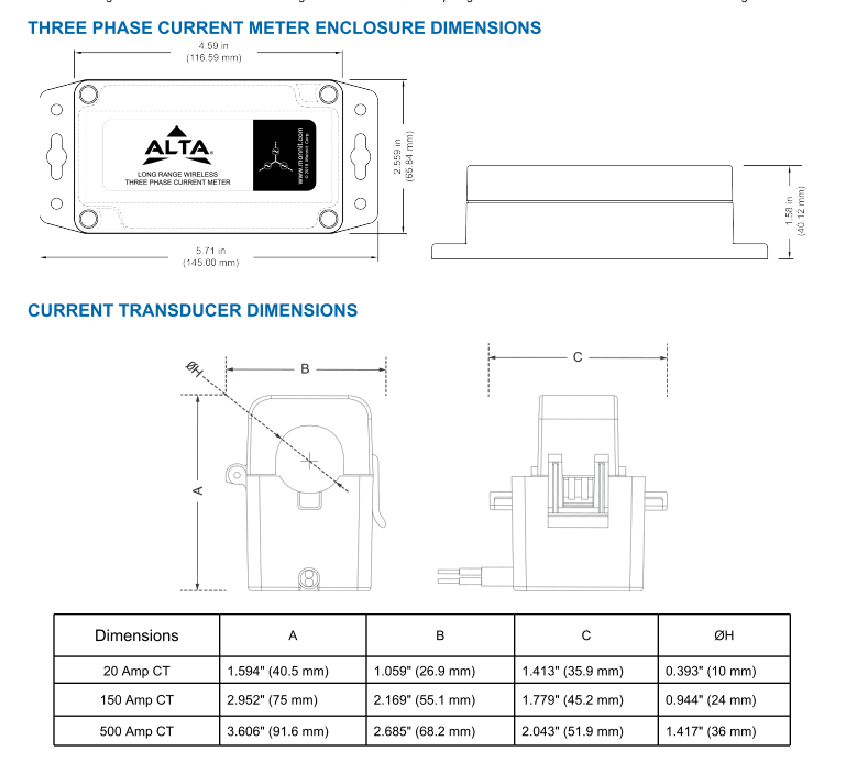
Dimensions of CTs:
20 Amp CT
A: 1.594" (40.5 mm)
B: 1.059" (26.9 mm)
C: 1.413" (35.9 mm)
ØH: 0.393" (10 mm)
150 Amp CT
A: 2.952" (75 mm)
B: 2.169" (55.1 mm)
C: 1.779" (45.2 mm)
ØH: 0.944" (24 mm)
500 Amp CT
A: 3.606" (91.6 mm)
B: 2.685" (68.2 mm)
C: 2.043" (51.9 mm)
ØH: 1.417" (36 mm)
[View Full Size]
Resources
20A, 150A, 500A Single Phase Current Meter User Guide
20A, 150A, 500A Three Phase Current Meter User Guide