Air Velocity Sensor Configuration and Installation Guide
Sensor Overview
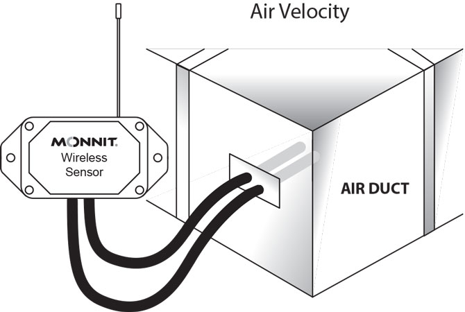
The Monnit ALTA Wireless Air Velocity Sensor measures the pressure difference between its two ports, accounts for ambient temperature and altitude, and determines HVAC system airflow speed in meters per second (m/s). The sensor helps HVAC technicians to prevent system failure and facility managers to maintain comfort and proper ventilation.
Settings to Configure
- Below (CFM)—Assessments below this value will cause the sensor to enter the Aware State.
- Above (CFM)—Assessments above this value will cause the sensor to enter the Aware State.
- Altitude—Enter the sensor’s altitude in meters above sea level for greater accuracy—default 0 Meters.
- Show Temperature—Shows Temperature with the Pressure Reading.
Additional Features and Options
- Scale—This sensor supports changing the unit of measurement from Fahrenheit to Celsius or vice versa. It also allows changing the Air Speed Scale to meters per second (Mps), miles per hour (mph), kilometers per hour (kmph), Knots (knot), cubic feet per minute (CFM), cubic meters per hour (CMH), and cubic meters per minute (CMM).
Installation Steps
Note: If this is your first time setting up your Monnit system, you must first set up your iMonnit account and connect your ALTA Gateway to iMonnit before registering your sensor. See this article for steps outlining how to get started: Creating an iMonnit account.
Step 1.
Remove the sensor from the package. If installing an industrial sensor, attach the antenna.
Step 2.
Register the sensor in iMonnit. Do not install the batteries until told to do so in iMonnit.
Step 3.
Determine the sensor’s installation location. We recommend placing the sensor in the location and making sure it reports to the gateway before final installation. See this article if you’re using an ALTA Site Survey Tool to perform a site survey to determine sensor installation location.
Step 4.
After ensuring that the sensor is communicating with the gateway, mount the sensor using the supplied screws or double-sided tape, leaving enough room for the sensor lead end to be inserted into the measurement port.
Step 5.
Secure the lead end to the port you wish to measure using the provided screws.
Note: When viewing the sensor from the front, the right inlet port is the positive or high side pressure input. This will be opposite of the lead end that has the high input on the left. Ensure the lead end is inserted into the duct you are measuring correctly for proper readings.
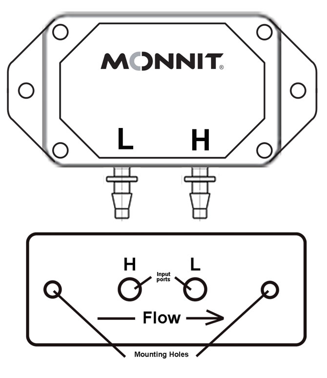
When the pressure on the right port is greater than the left port the sensor produces a negative pressure reading. When the pressure is greater on the left port the sensor produces a positive pressure reading. Combined with the temperature and the altitude, the sensor determines at what rate the air is flowing in a system.